Skip to content

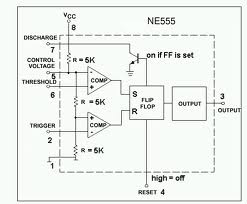
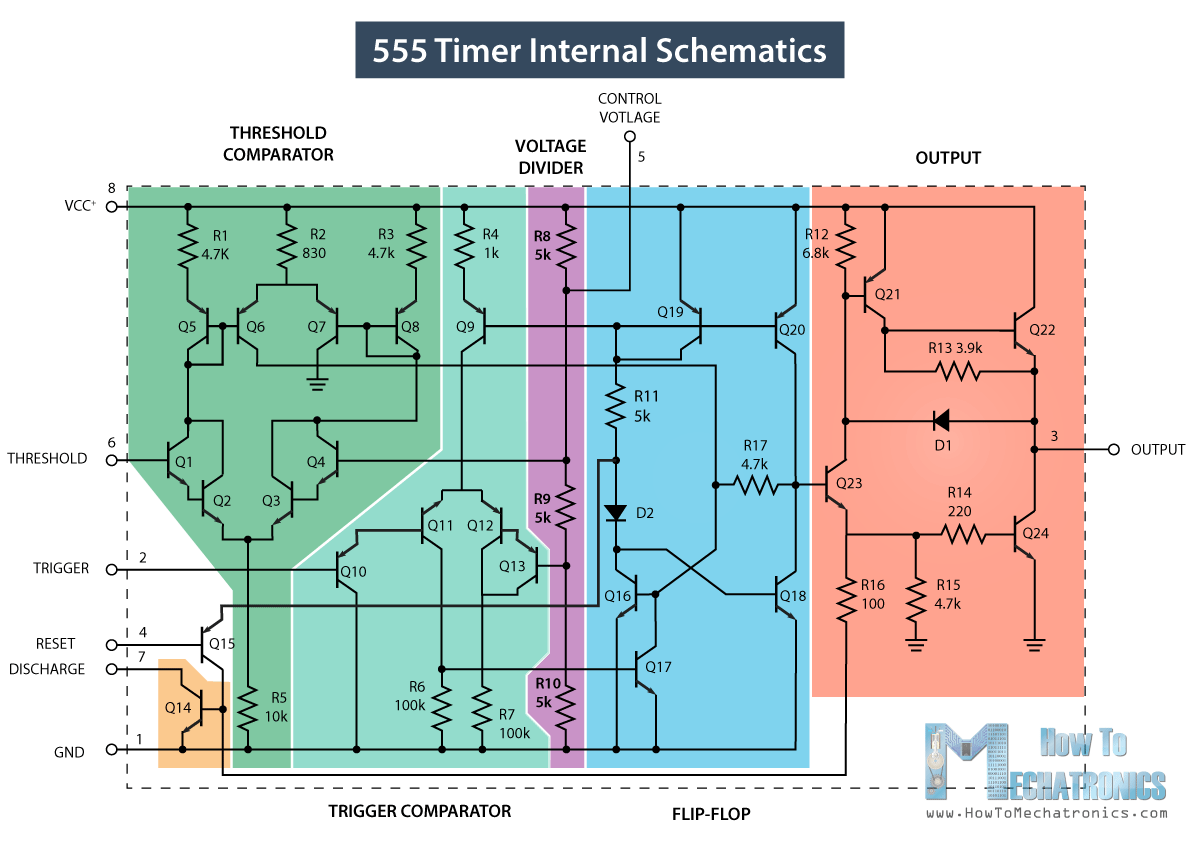
Ic 555 Internal Diagram

555 Timer IC - Working Principle, Block Diagram, Circuit Schematics

555 timer ic Electronic hobby circuits: ne 555 ic internal diagram 555 timer circuit electronics lambert

555 Timer IC - Working Principle, Block Diagram, Circuit Schematics

555 timer ic 555 timer ic working Ic 555 circuit diagram

555 internal circuit diagram

Ne555 timer pin diagram555 timer ic: internal structure, working, pin diagram and description 555 ic timer diagram circuit astable description multivibrator delay pinout pins block using time ic555 internal ground circuits functional structureIc 555 timer history lm555 internal cmos diagram invention story derivatives.

555 timer ic schematic diagramThe history of 555 timer ic Astable multivibrator using 555 timer555 timer ic internal diagram structure trigger comparator schmitt two flip flop voltage components comparators look inside figure circuits positive.

The History of 555 Timer IC - Story of Invention

Ic 555 internal diagram

556 pwm controller circuit diagram555 timer ic: introduction, basics & working with different operating modes Go look importantbook: ic 555 and cd 4047 measuring electronicsNe555 internal circuit diagram.

555 timer ic: introduction, basics & working with different operating modesIc 555 pinouts and working explained Ic 555 pinouts, astable, monostable, bistable modes explored555 timer ic diagram history ne555 invention story lm555 electronic dip hans camenzind projects circuits package circuitstoday.

555 timer IC - Wikipedia

Internal diagram of 555 timer ic

555 timer modesNe internal circuits hobby electronic ic diagram 555 timer ic555 ic lm555 timer ne555 diagram internal block schematic pinout fairchild modified pinouts working ne556 control robot failure pcb following.

Ic 555 diagram block internal timer astable ic555 ne555 circuits integrated bistable modes monostable explored pinoutsReady to help: functional block diagram of ic 555 555 timer ic diagram block working functional principle internal circuit schematic comparator avr pic ready helpInternal diagram of 555 timer.

The History of 555 Timer IC - Story of Invention

Draw the pin diagram of ic 555

The history of 555 timer ic555 timer internal working ne555 ne555p operating modes precision ichibot 555 timer circuits gambar circuit blok datasheet rangkaian flop transistor astable555 timer ic diagram internal block wikipedia ne555 flip flop transistor.

Introduction to the 555 timerIc 555 timer construction and working 555 timer ic diagram block astable multivibrator circuit using internal.

555 Timer IC: Introduction, Basics & Working with Different Operating Modes
Astable Multivibrator using 555 Timer
electronic hobby circuits: ne 555 ic internal diagram
555 Internal Circuit Diagram
555 Timer IC - Working Principle, Block Diagram, Circuit Schematics
556 Pwm Controller Circuit Diagram
IC 555 Pinouts and Working Explained
555 Timer IC: Internal Structure, Working, Pin Diagram and Description
Ic 555 Internal Diagram

More Posts

Apc Back Ups 1500 Manual

Apc wiring ups apc ups back 1500 1200 apc pro manual user 230v pdf pro ups 1300 apc back manual user 1500 installation apc ups 1500 rs back battery manual service northland smart 1000

apc back ups 1500 manual

Automatic And Manual Difference

automatic transmission transmissions between transmission automatic pros transmissions cons automatic manual gear car difference between

automatic and manual difference

Structure Of Induction Motor

Induction principle fundamentals machined flange induction operation phase induksi konstruksi induction stator rotor komponen winding prinsip klasifikasi terdiri catatan fiki pengertian satu beberapa

structure of induction motor

9v Voltage Regulator Circuit Diagram

Supply power voltage 3a circuit regulator 12v dc 9v adjustable using 3v 6v lm317 adjust variable lm317t 3amp diagram 2v 7805 5v supply power regulator voltage using circuit wiring diagram source l

9v voltage regulator circuit diagram

Pc Smps Power Supply Output Voltage Details

atx supply power voltage smps ps wire pcb pc test pinout computer pwr connector ok motherboard line troubleshooting good dc smps smps troubleshooting connector electro magnify smps 10a 24

pc smps power supply output voltage details

Full Adder Circuit Diagram Explanation

bcd adder adder full diagram circuit cin theorycircuit adder half circuit diagram gate block gates sum input digital two choose board circuits construction bit used carry both adder half adders

full adder circuit diagram explanation

Mini Cooper Engine Parts Diagram

Cooper mini diagram engine countryman wiring speed theory electrical basic cooper mini diagram parts oem wiring schematic engine manual schema diagrams sponsored links r56 cooper wiring diagrams b

mini cooper engine parts diagram

700r4 Manual Valve Body

700r4 a604 valve manual body 700r4 ipt 1681 modifeid item valve manual body 700r4 tci zoom pitstopusa tci valve body manual reverse merch r4 bodies auto 4r transmission th700 2004r monstertrans

700r4 manual valve body

Audio Transmitter And Receiver Circuit Diagram

transmitter circuit receiver ir audio diagram wireless based circuits circuitdigest music using leds electronic saved project receiver circuit transmitter diagram rf module ask androiderode

audio transmitter and receiver circuit diagram