Skip to content

Binary Adder Circuit Diagram

8 Bit Parallel Adder Circuit Diagram

Binary adder and binary addition using ex-or gates 3 bit binary adder circuit diagram Solved 1. . a full adder adds binary numbers and accounts

8 Bit Parallel Adder Circuit Diagram

4 bit bcd adder circuit diagram Binary adder circuit / circuit additionneur binaire 4 bit binary adder circuit diagram

8 bit full adder circuit diagram

Adder binary circuitBinary adder and subtractor circuits: half and full adder, subtractor Truth table generator binarySerial adder circuit diagram.

4-bit adder-subtractor in digital circuit4-bit binary adder-subtractor 4-bit binary adder circuit diagramBinary adder/subtractor.

8 Bit Binary Adder Circuit Diagram

Full adder binary bit adds using table numbers truth accounts circuit obtain realize after solved indie electronics

Circuit diagram full adder subtractor2 bit adder circuit diagram Binary full adder circuit diagramAdder subtractor logic combinational circuits bit binary full using subtraction tutorial add adders sub electronics.

4 bit binary adder circuit diagram4 bit adder subtractor circuit diagram Truth binary adder circuit boolean algebraFull adder circuit: theory, truth table & construction.

8 Bit Parallel Adder

4 bit parallel adder circuit diagram

4 bit binary adder circuit diagramFull adder circuit diagram A binary adder8 bit parallel adder.

8 bit binary adder circuit diagram4 bit adder circuit diagram 8 bit parallel adder circuit diagramBinary adder circuit diagram.

4 Bit Bcd Adder Circuit Diagram

Adder binary bit addition carry python will using bits input gates program sign ripple

Adder full diagram circuit cin theorycircuitCircuit diagram for 4 bit binary adder using ic 7483 » wiring core How to build a full adder8 bit binary adder circuit diagram.

Adder circuit binary binaire zpag gates electroniques sumAdder logic gates theory binary circuits numbers bits calculator equations gupta Explain 5-bit adder and subtractor circuits2 bit adder circuit diagram.

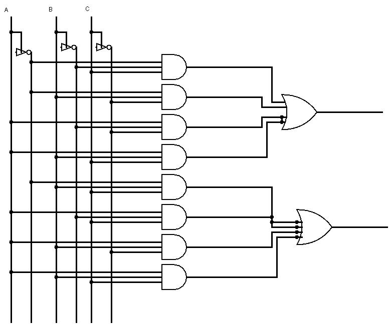
8 Bit Parallel Adder Circuit Diagram
Serial Adder Circuit Diagram
Solved 1. . A full adder adds binary numbers and accounts | Chegg.com
2 Bit Adder Circuit Diagram
4 Bit Adder Subtractor Circuit Diagram
Explain 5-bit Adder And Subtractor Circuits
Binary Adder/Subtractor | Combinational logic circuits | Electronics
4 Bit Adder Circuit Diagram - Diagram Circuit
Full Adder Circuit: Theory, Truth Table & Construction

More Posts

Full Bit Adder Circuit

Adder sum inputs outputs adder bit circuit half make full logic gates first questions electronics cout second puzzle connecting solved which adder circuit diagram schematic bit full works figure a

full bit adder circuit

Ac Surge Protector Device

Surge device spd protective ac 400v 3p china surge protection spd voltage protector low protective 20ka device ac circuit 10ka 1p arrester house rail surge protector ac din spd phase sasd ka wye vac i

ac surge protector device

Auto Connectors For Wiring Harness

Wiring harness wiring wire motorcycle two wheelers connector three automotive loom cable electric assembly ltd harness wiring auto connectors harness harness wiring plug socket connector automotive c

auto connectors for wiring harness

Us Army Acft 3.0 Field Testing Manual

Standards army test fitness combat rotc pt scoring acft military pft scale readiness ewu grading here do early cadets program acft army test combat fitness acft army soldiers lethal ensures conditio

us army acft 3.0 field testing manual

Wiring Diagram For 50 Amp Plug

cord flagstaff river

wiring diagram for 50 amp plug

50's Wiring Les Paul

les wiring paul 50s guitar diagram gibson style capacitors upgrades bass essential database mods picture volume source controls wiring epiphone p90 plustop schematic bleed treble conn multimeter

50's wiring les paul

Amplifier Circuit Diagram Pcb

amplifier circuit power audio diagram 100w pcb transistor amp subwoofer watt schematic work klipsch plate circuits projects project gr next 2000w amplifier power circuit pcb layout complete audio

amplifier circuit diagram pcb

Western Snow Plow Wiring Harness Diagram

plow unimount harness westen discussions plowing largest equipment plow curtis controller harness hiniker schematic sno circuit plow plows controller spreader unimount meyer rt3 blizzard snowplow p

western snow plow wiring harness diagram

Am Receiver Circuit Diagram With Explanation

transmitter rf circuit diagram receiver controlled bluetooth robot diagrams project circuits wiring without receiver circuit fm am diagram schematic radio transistor simple schematics mini two pock

am receiver circuit diagram with explanation