Implement 2 Bit By 2 Bit Multiplier
2 bit multiplier(हिन्दी ) Multiplier bit using adder schematic 2x2 multiplication binary single full types calculator given below figure Binary multiplier circuit solved
Solved Verilog code for the following diagram. [4 bit by 4 | Chegg.com
Multiplier circuit bit vhdl code modeling styles once look now Design example: two-bit by two-bit multiplier Implement 2 bit by 2 bit multiplier
Multiplier truth circuit logic behaviour value
Bit multiplier two comparator example coursesSolved figure 1 shows a 2-bit by 2-bit multiplier. write a Multiplier logic combinational binary geeksforgeeks output[diagram] 8 bit multiplier circuit diagram.
Array multiplier in digital logic2 bit by 2 bit multiplier Binary multiplierSolved design a decoder that maps each 4 bit hexadeci.
Bit multiplier binary
Pla structure of 2 × 2-bit multiplier.Solved . implement the 2-bitx2-bit multiplier circuit shown Array multiplier circuit diagramArchitecture and design of 16-bit multiplier module.
Multiplier 2x2 bit example coursesSolved how can you modify the 2-bit by 2-bit binary 4 bit multiplier circuit diagramDesign example: 2x2-bit multiplier.

2. implement a 6-bit multiplier by extending the
Multiplier bit circuit multisimMultiplier circuits multiplication multiply bits designing adders partial technobyte arithmetic Solved verilog code for the following diagram. [4 bit by 42 bit by 2 bit multiplier.
Pin on kelecBit multiplier sum partial multisim 2 bit multiplier circuit diagram2 bit by 2 bit multiplier.

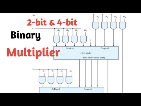
2-bit & 4-bit binary multiplier
Solved designing a 2-bit multiplier design a 2-bitCircuit diagram mux multiplier Solved construct a 3-bit by 4-bit binary multiplier circuit.Vhdl code for a 2-bit multiplier.
How to design a combinational circuit that will compare two 8-bitImplement 2 bit by 2 bit multiplier Multiplier verilog complementCircuit multiplier bit logic binary multiplication logisim digital two solved show applications numbers.
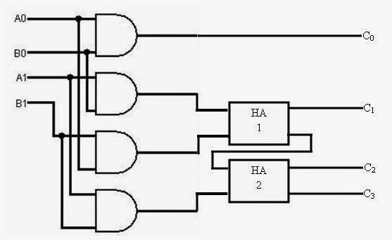
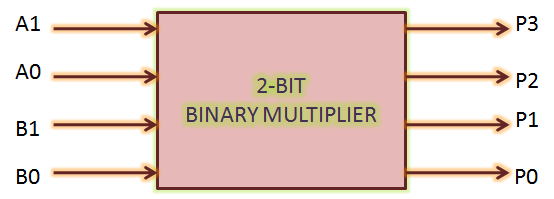
Implement 2 bit by 2 bit multiplier
How does a vbe multiplier work?Implement 2 bit by 2 bit multiplier 4 bit multiplier circuit diagramTruth table of a 2 bit multiplier.
.


![[DIAGRAM] 8 Bit Multiplier Circuit Diagram - MYDIAGRAM.ONLINE](https://i2.wp.com/www.researchgate.net/profile/Kailiang_Chen/publication/42437163/figure/fig21/AS:669375262650375@1536602907079/4-The-block-diagram-of-a-4-bit-signed-multiplier.ppm)

