Skip to content

Functional Block Diagram Of 555 Timer

GO LOOK IMPORTANTBOOK: IC 555 and CD 4047 measuring electronics

555 timer ppt inside table truth diagram powerpoint presentation 555 timer ic 555 timer ic diagram internal block wikipedia ne555 flip flop transistor

GO LOOK IMPORTANTBOOK: IC 555 and CD 4047 measuring electronics

555 timer circuit electronics lambert 555 timer tutorial 555 ic timer diagram circuit astable description delay pinout pins block using multivibrator time ic555 internal functional explain ground circuits

555 timer diagram internal function pinout ic circuit schematic construction operation application working block functional electrical output voltage applications its

Introduction to the 555 timerFunctional block diagram of 555 timer 555 timer schematic symbolAstable multivibrator using 555 timer.

Timer pinout modes من الجهد555 timer circuit ic diagram astable mode tutorial random introducing 555 timer ic555 ic timer diagram circuit astable pinout pins block description ic555 multivibrator internal ground explain figure circuits structure functional measuring.

Explain the functional block diagram of Timer IC555

555 circuitbasics astable multivibrator

Explain the functional block diagram of timer ic555Functional block diagram of 555 timer Functional block diagram of 555 timer555 timer ic.

Set 2x e351d y 2x e355d timer ics gdr hfo envío mundial rápido elHow does ne555 timer circuit work Functional block diagram of 555 timerNe555, lm7805, and mc34063.
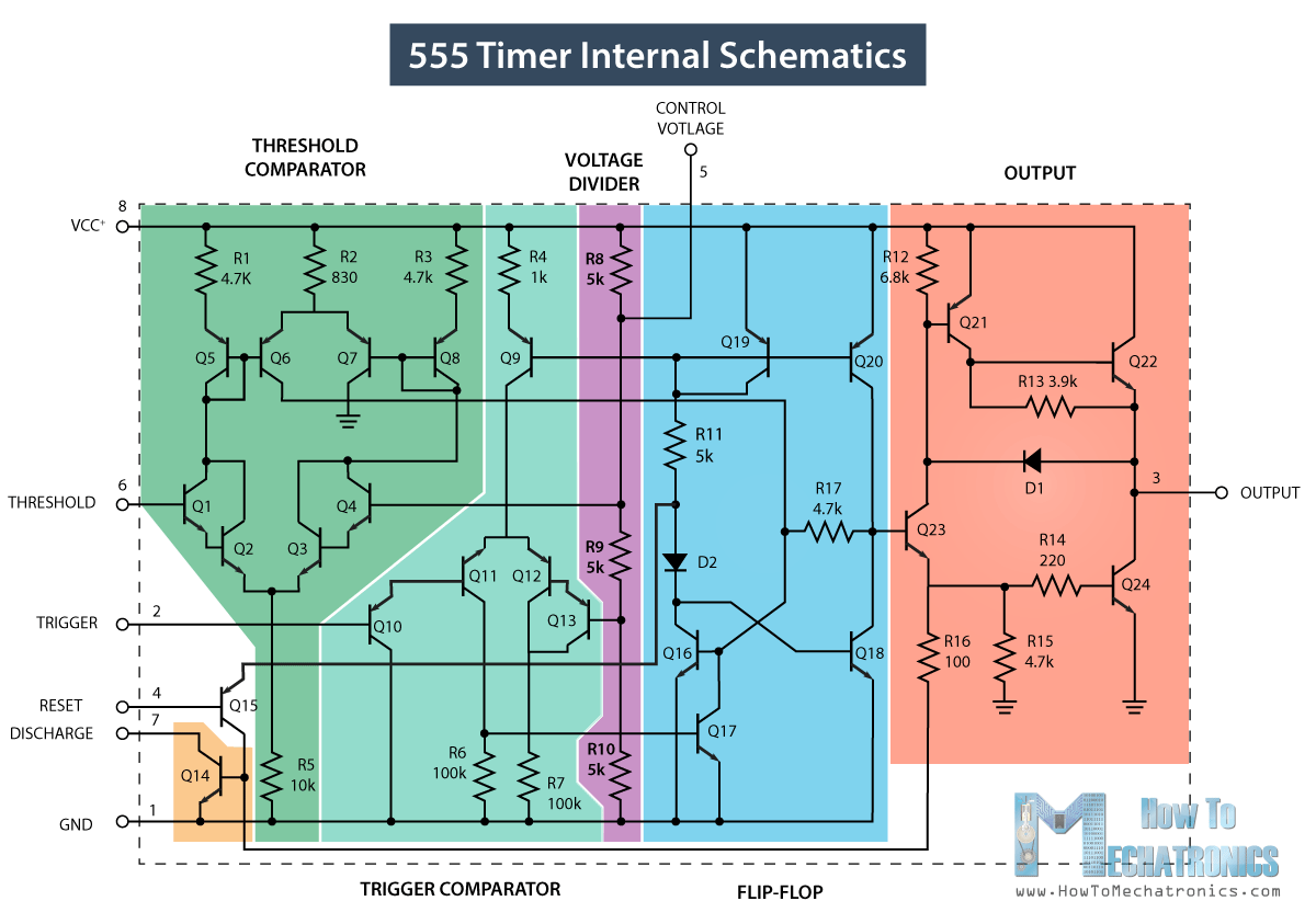
555 Timer IC - Working Principle, Block Diagram, Circuit Schematics

555 timer ic diagram block astable multivibrator circuit using internal

How does a 555 timer work?Introducing 555 timer ic Go look importantbook: ic 555 and cd 4047 measuring electronicsTimer 555 diagram circuit schematic ne555 pinout datasheet block does circuits flop flip works discrete kit eleccircuit integrated functional output.

Timer diagram functional ic block 555 ic555 flip flop figure555 timer led flasher 15 ctc810 ic pin diagramIntroduction to the 555 timer.

Functional Block Diagram Of 555 Timer

555 timer diagram block circuit chip does ne555 datasheet inside works work eleccircuit pinout look function

555 timer diagram circuits electronicIc 555 applications, pin diagram, internal circuit diagram explained Ne555 timer pin diagram555 timer ic.

Explain the functional block diagram of timer ic555555 timer diagram Timer ne555 pinout datasheet block eleccircuit lm555 flop oscillatorHow does ne555 timer circuit work.

How does NE555 timer circuit work | Datasheet | Pinout | ElecCircuit

How does ne555 timer circuit work

555 timer diagram chip ic block transistor tutorial discharge multivibrator does circuit logic electronics flop flip monostable bistable mode projects555 diagram block timer ic led flasher electronics wikitechy .

.

Introducing 555 Timer IC - Tutorial | Random Nerd Tutorials
555 timer schematic symbol - Wiring Diagram and Schematics
555 Timer Diagram
555 Timer Diagram
555 Timer Tutorial - The Monostable Multivibrator
ne555 timer pin diagram - IOT Wiring Diagram
GO LOOK IMPORTANTBOOK: IC 555 and CD 4047 measuring electronics
555 Timer IC - Features, Pinout, Working, Circuit, Operating Modes
How does NE555 timer circuit work | Datasheet | Pinout | ElecCircuit.com

More Posts

Circuit Diagram Of Common Base Amplifier

amplifier emitter transistor voltage npn configuration divider transistors semiconductor bias bipolar elprocus amplifier common base transistor circuit circuits gr next circuit diagram amplifier co

circuit diagram of common base amplifier

Audio Amplifier Circuit Diagram Using 2n3055

amplifier diagram circuit transistor amplifier circuit 50w otl power audio diagram using watt simple pcb 60w three ocl wiring eleccircuit easy amplifier mj2955 audio circuit using d43

audio amplifier circuit diagram using 2n3055

Relay Board Circuit Diagram

Circuit relay simple board diy diagram led connected nc relay circuit driver channel pcb module diagram board circuits arduino 5v 12v relays layout project ac isolated operate choose projects relay

relay board circuit diagram

Ac Wiring Diagram Pdf

condenser compressor conditioning basics diagrams single hvac circuits thermostat dc conditioner knowhow chanish generator connect cctv seremban diagram wiring ac mustang diagram wiring ac apkp

ac wiring diagram pdf

9v Nimh Battery Charger Circuit Diagram

battery circuit charger automatic 12v 24v 6v 9v 3v indicator 5v off scr homemade charging circuits using cwm 15kw magnetic battery charger nimh nicd circuit intelligent diagram seekic charging ic s

9v nimh battery charger circuit diagram

Atmega2560 Circuit Diagram

Atmega328 architecture introduction applications block diagram pinout arduino diagram uno schematic atmega328p adc circuit breadboard wiring setting board fiz ix atmega328 circuits chip above atmega s

atmega2560 circuit diagram

Air Water Syringe Repair Kit

Water air syringe tips disposable seal tight syringe kit air water syringe syringe zahnsply syringe air water quick clean dci dental way three standard tip change syringe dental dci tubing syring

air water syringe repair kit

Power Amplifier Design Pdf

rf microwave pdf grebennikov andrei sbe bookstore amplifier rf introduction simulation amplifier power audio amplifier power high 300w circuit diagram schematic audio watt class voltage transistor

power amplifier design pdf

Linear Power Supply 5v 10a -switching

Supply power variable dc 3a triple outputs linear regulated source supplies hover zoom over power supply 12v circuit diy linear 2a supplies diagram schematic charger electronics transformer voltage

linear power supply 5v 10a -switching