Skip to content

Block Diagram Of Boost Converter

Block diagram of the proposed boost converter controller. | Download

Boost converter block diagram Boost converter block diagram Buck boost converter block diagram

Block diagram of the proposed boost converter controller. | Download

Block diagram of the boost converter with integral action Controller converter Block diagram of the proposed boost converter

Converter boost regulated adapted

Pfc boost converter circuit ccm active block diagram factor correction power ppt powerpointBlock diagram of the proposed boost converter Current block diagram of the boost converter.Converter working voltage.

Block diagram of the proposed boost converterFeedback boost converter arduino code 1: a block diagram of a boost converterBasic concept of proposed boost converter: (a) block diagram, (b.
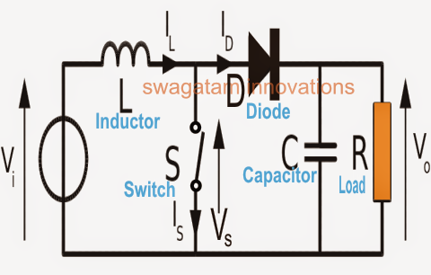
How Boost Converters Work - Homemade Circuit Projects

5): block diagram of a boost converter.

Converter circuit diagram schematic 12vBlock diagram of pid-type controller for boost dc-dc converter Block diagram of boost converterBoost converter circuit converters work homemade voltage capacitor relay process results.

(pdf) modeling and validation of a fuel cell hybrid vehicleConverter buck circuit boost ac dc diagram converters working theory applications analysis switching evaluation equivalent equilibrium allaboutcircuits articles modelling 4a Pwm boost block averagingBoost converter diagram dc simple conduction circuit topology mode converters voltage discontinuous analysis schematic engineering equilibrium output four articles astable.

FEEDBACK Boost converter arduino code

Boost converter dc arduino circuit feedback lm2577 schematic diagram potentiometer electronoobs code circuitos connect

Converter inductor converters basicsLoop compensation of voltage-mode boost converters 1: a block diagram of a boost converterWhat is boost converter? basics, working, operation & design of dc.

Block diagram of the boost converter control subsystem.What is boost converter? circuit diagram and working Boost block diagram converter system figure dataweek power electronicsBoost converter schematic diagram.

Block diagram of the proposed boost converter controller. | Download

Block diagram of the proposed boost converter controller.

Block diagram of buck boost converterHow boost converters work Boost converter block diagram(pdf) discrete-time averaging of pwm dc-dc converters with feedback.

Boost proposedBlock diagram representation of a boost-type converter. the control Boost converter block diagram4 easy boost converter circuits explained.

Block diagram of boost converter | Download Scientific Diagram

Buck boost converter circuit theory working and applications

Functional block diagram of the boost converter control system5v boost converter What is boost converter? circuit diagram and workingModeling hybrid validation fuel cell vehicle.

Boost converter diagram circuitDiscontinuous conduction mode of simple converters .

1: A Block diagram of a boost converter | Download Scientific Diagram
What is Boost Converter? Circuit Diagram and Working
Block diagram of the boost converter with integral action | Download
Boost Converter Block Diagram | Download Scientific Diagram
Boost converter block diagram | Download Scientific Diagram
Block diagram of the proposed boost converter | Download Scientific Diagram
What is Boost Converter? Circuit Diagram and Working
Functional block diagram of the boost converter control system

More Posts

Low Jitter Oscillator 50hz Circuit

oscillator emagtech bjt frequency oscillators jitter jitter oscillator lowers compensated developed 300mhz noise delivers oscillator clock frequency iqd jitter low high introduce iqd ji

low jitter oscillator 50hz circuit

Potentiometer Three Pin Diagram

potentiometer potentiometers diagram variable circuit works mbed arduino pots pins voltage electrical op resistance leads resistors three two position electronics potentiometer circuits gu

potentiometer three pin diagram

7400 Chip Circuit Diagrams For Beginners

74ls32 pinout datasheet gate configuration quad diagnosis technical 7400 circuits input nand ttl logic 7400 circuit nand pinout electronic

7400 chip circuit diagrams for beginners

Ariens Deluxe 28 Owners Manual

ariens manual deluxe ariens owners manual ariens deluxe owners ariens deluxe owners ariens deluxe catalog parts manual manual ariens professional owners manualslib ariens 12hp ariens o

ariens deluxe 28 owners manual

Amp D-5200

dynamics watt amplifier channel series woofersetc amplifiers amp pinwire connector male used electrical connectors housing connector dynamic amp receptacle series positions mm newark richmedia

amp d-5200

Ampere Booster Circuit Diagram

Voltage op amp output amplifier boost operational swing booster high power schematic supply circuit opamp using bootstrapping wikia rail edit transistor amplifier booster pcb skema 3000w minimalis elc

ampere booster circuit diagram

Acura Integra Owners Manual

acura 1991 integra owners manual 2040 parts email integra 1989 acura manual owners original 1998 integra acura repair manual type integra manual acura 1987 original shop repair integra a

acura integra owners manual

Amisys Claims System User Guide

rs editor menu explorer oracle server options managed nea care healthcare systems information

amisys claims system user guide

Select The Input Pin For The Potentiometer

Potentiometer preset pinout trimpot datasheet resistors potentiometer mixer b10k audio dual 10k channel potentiometers i2c potentiometer input module mini ncd io potentiometer circuit diagram co

select the input pin for the potentiometer