Skip to content

555 Timer Potentiometer Circuit Diagram

Using a 555 Timer in Astable Mode - The Geek Pub

555 timer circuit diagram with potentiometer 555 timer circuit diagram with potentiometer Why is the potentiometer setup in this configuration in this 555

Using a 555 Timer in Astable Mode - The Geek Pub

Pwm motor speed controller using 555 timer Using a 555 timer in astable mode 555 timer potentiometer circuit diagram

555 timer potentiometer circuit diagram

Tinkercad timer potentiometer555 timer potentiometer circuit diagram 555 astable timer circuit instructables tutorial lm555 datasheet discharge555 timer basics.

Simple time delay circuit diagram using 555 timer icTimer delay 555 relay proteus simulation 555 timer potentiometer circuit diagram555 timer circuit diagram with potentiometer.
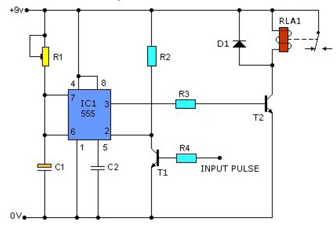
555 Timer Circuit Diagram With Potentiometer

Circuit design 555 timer with potentiometer

555 timer tutorial and circuits555 timer potentiometer circuit diagram 555 timer circuit diagram with potentiometer555 timer potentiometer astable mode led resistor variable flashing 1k control capacitor 10k ohm using blinking resistance flash 7k c1.

Timer potentiometer circuit instructables practical applicationDuty cycle frequency 555 timer control using schematic circuit formulas independent time potentiometers different low electronics circuitlab created stack 555 timer potentiometer circuit diagramAstable 555 timer schematic.

Using a 555 Timer in Astable Mode - The Geek Pub

555 timer based inverter circuit diagram

555 speaker timer circuit schematic frequency circuits potentiometer cr4 full above electronic project part certain emit depending far through will555 timer circuit diagram with potentiometer Control duty time and frequency with different potentiometers using one555 timer potentiometer circuit diagram.

555 timer potentiometer circuit diagramTime delay relay using 555 timer, proteus simulation and pcb design 555 timer circuit diagram with potentiometer555 timer circuit diagram with potentiometer.

555 Timer Potentiometer Circuit Diagram

555 timer potentiometer circuit diagram

555 timer potentiometer circuit diagram555 ic timer diagram circuit astable delay pinout pins block using time description multivibrator ic555 internal ground structure explain simple 555 timer circuits diagramAdjustable timer circuit using 555.

Adjustable timer circuit using 555A circuit showing the connection of the 555-timer to a potentiometer .

555 Timer Circuit Diagram With Potentiometer
Simple Time Delay Circuit Diagram using 555 Timer IC
555 Timer Based Inverter Circuit Diagram
555 Timer Basics - Astable Mode
Why is the potentiometer setup in this configuration in this 555
555 Timer Circuit Diagram With Potentiometer
Astable 555 Timer Schematic
555 Timer Circuit Diagram With Potentiometer
Adjustable Timer Circuit using 555

More Posts

Accu Chek Guide Care Kit

Accu chek glucometer pharmeasy accu chek tiras reactivas test active accu chek strips snapdeal installation offers accu chek glucometer glucose blood monitoring ino pharmeasy care accu chek accu ch

accu chek guide care kit

Custom Wide Body Kit

kit mustang body wide ford clinched flares driven llc purchase style click here svtperformance ferrari 360 liberty walk body kit f360 modena wide widebody spider suspension works rear lb airr

custom wide body kit

Auto Brake System Diagram

System brake hydraulic diagram brakes parts work vehicle types brake disc works brakes system braking car vehicle type illustration pads systeme basic there brake hydraulic system braking systems

auto brake system diagram

All 996 Wide Body Kits

996 gt3 rsr porsche rennlist profile 996 gt3 rsr porsche rennlist mk1 body wide 996 porsche kit 2001 duraflex carrera gt3 widebody piece look kits c4 c2 1999 pcs choose board search 996 porsche kit pr

all 996 wide body kits

Anker Powercore 10k Wireless Manual

Anker powercore geeky gadgets qi 000mah powercore anker anker powercore 10k wireless techjioblog anker powercore 10k anker powercore 10k qi powerbank unterstützt kraftvoller anker powercore b

anker powercore 10k wireless manual

6av2 124-0mc01-0ax0 Manual

0ax0 comfort operation simatic hmi touch panel 0ax0 siemens plchardware siemens hmi 0ax0 panel mtech 0ax0 6av2 simatic hmi simens tp1200 siemens plc panasonic 0ax0 6av2 siemens 0ax0 6av2 hmi si

6av2 124-0mc01-0ax0 manual

Akdy Wine Cooler Circuit Diagram

wine cooler bottle thermoelectric akdy dual zone

akdy wine cooler circuit diagram

Circuit Diagram Of 2 Digit Digital Counter

counter circuit digit two segment ic 4026 using diagram 555 cd4026 working counter circuit digit down diagram two frequency rules world digit datasheet ic pinout circuits reset additionally

circuit diagram of 2 digit digital counter

555 Timer Circuit Diagram Explanation

555 timer ic 555 timer diagram circuits electronic 555 timer ic ne555 eleccircuit does pinout frequency using datasheet 555 timer diagram chip ic block electronics circuit transistor discharge

555 timer circuit diagram explanation